FURSE_Lightning protection device FURSE_ESP 415 M1R

Product Noï¼ڑPro200941494631
Product Modelï¼ڑESP 415 M1R
UpdateTimeï¼ڑ
Viewsï¼ڑ1392

Detailsï¼ڑ

![]()
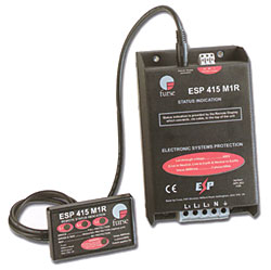
![]() Remote display is easily installed with standard drilling tools.
Remote display is easily installed with standard drilling tools.![]() Remote display comes with integral fixings and a panel drilling template.
Remote display comes with integral fixings and a panel drilling template.![]() Compact size for installation in the power distribution board.
Compact size for installation in the power distribution board.![]() Maintenance free.
Maintenance free.
Installation
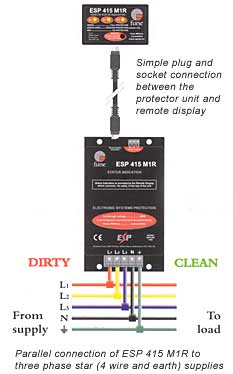
Installation of the protector unit is identical to the ESP 415 M1. Position remote display, making sure that the cable is long enough, is unimpeded within the cabinet, and allows a minimum of 60mm behind the panel front (for the interconnection cable). Use template (found in installation instructions supplied with each unit) to mark holes. Drill, screw in place and plug in connection cable on back of display from inside the cabinet.
Suitable Accessories
In applications where a 1 metre connecting cable is insufficient, a 4 metre cable (ESP RLA-4) can be ordered separately.
Electrical Specification
| ESP 415 M1R | |
| Nominal voltage (RMS) | 415V |
| Working voltage (RMS) | 346-484V |
| Frequency range | 40-60Hz |
| Current rating (supplyl) | Direct connection to supplies up to 100A Connection via series fuses to supplies greater than 100A See installation instructions |
| Leakage current (to earth) | <250آµA |
| Indicator circuit current | <10mA |
| Volt free contact current rating nominal voltage (RMS) |
Screw terminal 1A 250V |
Under fault conditions the remote display will go blank if the L1 phase loses powere or becomes faulty. This is due to the isolation requirements needed for circuitry mounted externally to the main protector unit.
Transient Specification
| ESP 415 M1R | |
| Let-through voltage - all conductors (note 1) 6kV, 1.2/50آµs open circuit voltage 3kA 8/20آµs short circuit current to: BS 6651:1999 Appendix C, Cata C-Low & B-High IEEE C62.41-1991 (note 2) Location Cats C1 & B3 SS CP 33:1996 Appendix F AS 1768-1991 Appendix B, Cat B UL1449 mains wire-in |
600V |
| 4kV 1.2/50آµs open circuit voltage 2kA 8/20آµs short circuit current to: IEC 1000-4-5:1995 |
570V |
| 2kV 1.2/50آµs open circuit voltage 1kA 8/20آµs short circuit current |
530V |
| 5kA 8/20آµs to NFC 61-740 | 690V |
| 2.5kA 8/20آµs to BS EN 60099-1:1994 | 590V |
| 6kV 0.5آµs 100kHz ring wave, 500A to: IEEE C62.41-1991 (note 2) Location Cat B3 AS 1768-1991 Appendix B, Cat B |
510V |
| Maximum surge current (note 3) between any two conductors total unit to earth |
30kA 120kA |
1 The maximum transient voltage let-through the protector throughout the test (+/-5%) phase to neutral, phase to earth and neutral to earth.
2 Formerly IEEE 587 and ANSCI C62.41
3 Tested with 8/20آµs waveshape to BS 6651:1999 Appendix C. Note: the electrical system external to the unit may constrain the actual current rating achieved in a particular installation.
Mechanical Specification
| ESP 415 M1R | |
| Temperature range | -40آ°C to +70آ°C |
| Connection type | Screw terminal |
| Conductor size (stranded) | 16mm2 |
| Earth connection | Screw terminal |
| Volt free contact | Connect via screw terminal with conductor up to 2.5mm2 (stranded) |
| Display connection | 6 way interconnection cable (1 metre) |
| Weight unit packaged |
1.1kg 1.2kg |
 | |
Downloadï¼ڑ
 ESP415M1R.pdf