Lightning Protection Products

DEHNventil M TT (FM)
")
Product NoпјҡPro200963163957
Product ModelпјҡDEHNventil M TT (FM)
UpdateTimeпјҡ
Viewsпјҡ1077

Detailsпјҡ
DEHNventil M TT (FM)
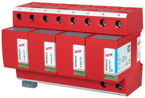

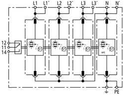
DEHNventil M TT (FM) Dimension drawing DV M TT 255 (FM) Basic circuit diagram DV M TT 255 FM
DV M TT 255 (FM): Modular combined lightning current and surge arrester for use in TT and TN-S systems (3+1 circuit)
| DV M TT 255 | DV M TT 255 FM | ||||||||||||||||||
| SPD according to EN 61643-11 | Type 1 | Type 1 | |||||||||||||||||
| SPD according to IEC 61643-1 | Class I | Class I | |||||||||||||||||
| Energy-coordinated protection effect with regard to the terminal equipment | Type 1 + Type 2 | Type 1 + Type 2 | |||||||||||||||||
| Energy-coordinated protection effect with regard to the terminal equipment (вүӨ 5m) | Type 1 + Type 2 + Type 3 | Type 1 + Type 2 + Type 3 | |||||||||||||||||
| Nominal a.c. voltage [UN] | 230 / 400 V | 230 / 400 V | |||||||||||||||||
| Max. continuous operating a.c. voltage [UC] | 255 V | 255 V | |||||||||||||||||
| Lightning impulse current (10/350 Вөs) [L1+L2+L3+N-PE] [Itotal] | 100 kA | 100 kA | |||||||||||||||||
| Lightning impulse current (10/350 Вөs) [L-N] [Iimp] | 25 kA | 25 kA | |||||||||||||||||
| Lightning impulse current (10/350 Вөs) [N-PE] [Iimp] | 100 kA | 100 kA | |||||||||||||||||
| Nominal discharge current (8/20 Вөs) [In] | 25 / 100 kA | 25 / 100 kA | |||||||||||||||||
| Voltage protection level [L-N] [UP] | вүӨ 1.5 kV | вүӨ 1.5 kV | |||||||||||||||||
| Voltage protection level [N-PE] [UP] | вүӨ 1.5 kV | вүӨ 1.5 kV | |||||||||||||||||
| Follow current extinguishing capability [L-N] a.c. [Ifi] | 50 kArms | 50 kArms | |||||||||||||||||
| Follow current extinguishing capability [N-PE] a.c. [Ifi] | 100 Arms | 100 Arms | |||||||||||||||||
| Follow current limitation/Selectivity | no tripping of a 20 A gL/gG fuse up to 50 kArms (prosp.) | no tripping of a 20 A gL/gG fuse up to 50 kArms (prosp.) | |||||||||||||||||
| Response time [tA] | вүӨ 100 ns | вүӨ 100 ns | |||||||||||||||||
| Max. backup fuse (L) up to IK = 50 kArms | 315 A gL/gG | 315 A gL/gG | |||||||||||||||||
| Max. backup fuse (L) for IK > 50 kArms | 200 A gL/gG | 200 A gL/gG | |||||||||||||||||
| Max. back-up fuse (L) up to IK = 25 kArms | A gL/gG | A gL/gG | |||||||||||||||||
| Max. back-up fuse (L) up to IK = 25 kArms | A gL/gG | A gL/gG | |||||||||||||||||
| Max. backup fuse (L-LВҙ) | 125 A gL/gG | 125 A gL/gG | |||||||||||||||||
| Temporary overvoltage (TOV) [L-N] [UT] | 440 V / 5 sec. | 440 V / 5 sec. | |||||||||||||||||
| Temporary overvoltage (TOV) [N-PE] [UT] | 1200 V / 200 ms | 1200 V / 200 ms | |||||||||||||||||
| Operating temperature range (parallel connection) [TUP] | -40В°C...+80В°C | -40В°C...+80В°C | |||||||||||||||||
| Operating temperature range (series connection) [TUS] | -40В°C...+60В°C | -40В°C...+60В°C | |||||||||||||||||
| Operating state/fault indication | green / red | green / red | |||||||||||||||||
| Cross-sectional area (L1, L1, L2, L2, L3, L3, N, N, PE, |
10 mm2 solid/flexible | 10 mm2 solid/flexible | |||||||||||||||||
| Cross-sectional area (L1, L2, L3, N, PE) [max.] | 50 mm2 stranded/35 mm2 flexible | 50 mm2 stranded/35 mm2 flexible | |||||||||||||||||
| Cross-sectional area (L1, L2, L3, N, |
35 mm2 stranded/25 mm2 flexible | 35 mm2 stranded/25 mm2 flexible | |||||||||||||||||
| For mounting on | 35 mm DIN rail acc. to EN 60715 | 35 mm DIN rail acc. to EN 60715 | |||||||||||||||||
| Enclosure material | red thermoplastic, UL 94 V-0 | red thermoplastic, UL 94 V-0 | |||||||||||||||||
| Degree of protection | IP 20 | IP 20 | |||||||||||||||||
| Dimension | 8 mods., DIN 4 | 8 mods., DIN 4 | |||||||||||||||||
| Approvals, Certifications | KEMA, VDE, UL, VdS | KEMA, VDE, UL, VdS | |||||||||||||||||
| Type of remote signalling contact | -- | changeover contact | |||||||||||||||||
| Switching capacity a.c. | -- | 250 V/0.5 A | |||||||||||||||||
| Switching capacity d.c. | -- | 250 V/0.1 A; 125 V/0.2 A; 75 V/0.5 A | |||||||||||||||||
| Cross-sectional area for remote signalling terminals | -- | max. 1.5 mm2 solid/flexible | |||||||||||||||||
| PU | 1 pcs. | 1 pcs. | |||||||||||||||||
| ordering information | |||||||||||||||||||
| Type | DV M TT 255 | DV M TT 255 FM | |||||||||||||||||
| Part No. | 951 310 | 951 315 | |||||||||||||||||