Lightning Protection Products

DEHNbloc DB M 1 150/255 FM

Product NoпјҡPro20096314285
Product ModelпјҡDEHNbloc DB M 1 150/255 FM
UpdateTimeпјҡ2010.06.02
Viewsпјҡ1819

DEHNbloc DB M 1 150/255 FM
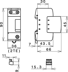
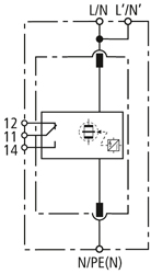
DEHNbloc M 1 ... FM Dimension drawing DEHNbloc DB M 1 150/255 FM Basic circuit diagram DEHNbloc DB M 1 150/255 FM
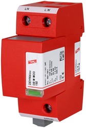
DEHNbloc DB M 1 150/255 FM: Single-pole modular coordinated lightning current arrester with high follow current limitation; with remote signalling contact for monitoring systems (floating changeover contact)
| DB M 1 150 FM | DB M 1 255 FM | ||||||||||||||||||
| SPD according to EN 61643-11 | Type 1 | Type 1 | |||||||||||||||||
| SPD according to IEC 61643-1 | Class I | Class I | |||||||||||||||||
| Max. continuous operating a.c. voltage [UC] | 150 V | 255 V | |||||||||||||||||
| Lightning impulse current (10/350 Ојs) [Iimp] | 35 kA | 50 kA | |||||||||||||||||
| Nominal discharge current (8/20 Ојs) [In] | 35 kA | 50 kA | |||||||||||||||||
| Voltage protection level [UP] | 1.5 kV | 2.5 kV | |||||||||||||||||
| Follow current extinguishing capability a.c. [Ifi] | 50 kArms | 50 kArms | |||||||||||||||||
| Follow current limitation/Selectivity | no tripping of a 32 A gL/gG fuse up to 50 kArms (prosp.) | no tripping of a 32 A gL/gG fuse up to 50 kArms (prosp.) | |||||||||||||||||
| Response time [tA] | вүӨ 100 ns | вүӨ 100 ns | |||||||||||||||||
| Max. backup fuse (L) up to IK = 50 kArms (ta вүӨ 0.2 s) | 500 A gL/gG | 500 A gL/gG | |||||||||||||||||
| Max. backup fuse (L) up to IK = 50 kArms (ta вүӨ 5 s) | 315 A gL/gG | 315 A gL/gG | |||||||||||||||||
| Max. backup fuse (L) for IK > 50 kArms | 200 A gL/gG | 200 A gL/gG | |||||||||||||||||
| Max. backup fuse (L-L) | 125 A gL/gG | 125 A gL/gG | |||||||||||||||||
| Temporary overvoltage (TOV) [UT] | 200 V / 5 sec. | 440 V / 5 sec. | |||||||||||||||||
| Operating temperature range (parallel connection) [TUP] | -40В°C...+80В°C | -40В°C...+80В°C | |||||||||||||||||
| Operating temperature range (series connection) [TUS] | -40В°C...+60В°C | -40В°C...+60В°C | |||||||||||||||||
| Operating state/fault indication | green / red | green / red | |||||||||||||||||
| Cross-sectional area (L/N, L/N, N/PE (N)) min. | 10 mm2 solid/flexible | 10 mm2 solid/flexible | |||||||||||||||||
| Cross-sectional area (L/N, N/PE(N)) max. | 50 mm2 stranded/35 mm2 flexible | 50 mm2 stranded/35 mm2 flexible | |||||||||||||||||
| Cross-sectional area (L/N) max. | 35 mm2 stranded/25 mm2 flexible | 35 mm2 stranded/25 mm2 flexible | |||||||||||||||||
| For mounting on | 35 mm DIN rail acc. to EN 60715 | 35 mm DIN rail acc. to EN 60715 | |||||||||||||||||
| Enclosure material | red thermoplastic, UL 94 V-0 | red thermoplastic, UL 94 V-0 | |||||||||||||||||
| Degree of protection | IP 20 | IP 20 | |||||||||||||||||
| Dimension | 2 mods., DIN 4 | 2 mods., DIN 4 | |||||||||||||||||
| Type of remote signalling contact | changeover contact | changeover contact | |||||||||||||||||
| Switching capacity a.c. | 250 V/0.5 A | 250 V/0.5 A | |||||||||||||||||
| Switching capacity d.c. | 250 V/0.1 A; 125 V/0.2 A; 75 V/0.5 A | 250 V/0.1 A; 125 V/0.2 A; 75 V/0.5 A | |||||||||||||||||
| Cross-sectional area for remote signalling terminals | max. 1.5 mm2 solid/flexible | max. 1.5 mm2 solid/flexible | |||||||||||||||||
| 1 pcs. | 1 pcs. | ||||||||||||||||||
| ordering information | |||||||||||||||||||
| Type | DB M 1 150 FM | DB M 1 255 FM | |||||||||||||||||
| Part No. | 961 115 new! | 961 125 new! | |||||||||||||||||