Furse - Protectors for Rail Applications

Product Noï¼ڑPro200962113620
Product Modelï¼ڑesp ssi/m, esp ssi/b, esp ssi/120ac, esp ssi/140ac, esp 12
UpdateTimeï¼ڑ
Viewsï¼ڑ1039

Detailsï¼ڑ
![]() Network Rail approved protectors for SSI mains power and data links.
Network Rail approved protectors for SSI mains power and data links.![]() For single phase mains power supplies of 90–150 volts, use the ESP SSI/120AC (formerly ESP 120X).
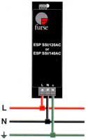
For single phase mains power supplies of 90–150 volts, use the ESP SSI/120AC (formerly ESP 120X).![]() For single phase mains power supplies of 90–165 volts, use the ESP SSI/140AC (formerly S065).
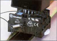
For single phase mains power supplies of 90–165 volts, use the ESP SSI/140AC (formerly S065).![]() For SSI data links, use the ESP SSI/B base unit with the ESP SSI/M protection module.
For SSI data links, use the ESP SSI/B base unit with the ESP SSI/M protection module.
Application
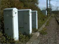
To prevent transient overvoltage damage to Solid State Interlocking (SSI) systems, protectors should be fitted in trackside cabinets and equipment rooms, on both the data link and the mains power lines.
Features and benefits
![]() Accepted for use on Network Rail infrastructure. NRS PADS references: ESP
Accepted for use on Network Rail infrastructure. NRS PADS references: ESP
SSI/M - 086/047066; ESP SSI/B - 086/047067; ESP SSI/120AC - 086/047058
and ESP SSI/140AC - 086/047059.![]() Very low let-through voltage between all sets of conductors (ESP SSI/120AC and ESP SSI/140AC) and all signal lines (ESP SSI/M).
Very low let-through voltage between all sets of conductors (ESP SSI/120AC and ESP SSI/140AC) and all signal lines (ESP SSI/M).![]() Provide repeated protection in lightning intense environments.
Provide repeated protection in lightning intense environments.![]() ESP SSI/B modified base unit can be permanently wired into the system.
ESP SSI/B modified base unit can be permanently wired into the system.![]() ESP SSI/M plug-in protection module can be replaced without interfering with the operation of the system.
ESP SSI/M plug-in protection module can be replaced without interfering with the operation of the system.![]() ESP SSI/B incorporates a 100Q terminating resistance that can be connected if required.
ESP SSI/B incorporates a 100Q terminating resistance that can be connected if required.![]() ESP SSI/B can be flat mounted, or a built-in DIN rail foot allows simple clip-on mounting to top-hat or G DIN rails.
ESP SSI/B can be flat mounted, or a built-in DIN rail foot allows simple clip-on mounting to top-hat or G DIN rails.![]() ESP SSI/120AC and ESP SSI/140AC are a compact size for easy installation in trackside cabinets and control rooms.
ESP SSI/120AC and ESP SSI/140AC are a compact size for easy installation in trackside cabinets and control rooms.![]() ESP SSI/120AC and ESP SSI/140AC have three way visual indication of protector status and advanced pre-failure warning.
ESP SSI/120AC and ESP SSI/140AC have three way visual indication of protector status and advanced pre-failure warning.![]() Maintenance free.
Maintenance free.
Network Rail Certification
All the products on this page have Network Rail Certificates of Acceptance, allowing them to be used on Network Rail infrastructure.
Installation
Connect in series with the datalink either near where it enters the trackside location cabinet or the equipment room.
ESP SSI/120AC and ESP SSI/140AC
Install in parallel, within the trackside cabinet or equipment room. The protector should be installed on the load side of the fuses, at the secondary side of the step-down transformer.
Connect, with very short leads, to phase (BX), neutral (NX or CNX) and earth. SSI supplies are generally under 100A, but if they exceed this level, the phase/live connecting leads should be fused.
| ESP SSI/M | |
| Maximum signal voltage | 7V |
| Maximum common mode stand-off voltage | 90Vrms |
| Current rating | 100mA |
| In-line resistance | 4.5ohms |
| Leakage (Line to line impedance) (Line to earth impedance) |
1ohm |
| Differential Bandwidth (50ohm system) | 10MHz |
| ESP SSI/B |
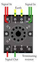
| This is a modified 11 pin `relay type socket containing a 10052 آ±5% wire-wound 2.5W resistor connected between terminals 8 and 9. Internal links between terminals 2 & 3, 9 & 10, and 1 & 11. |
| ESP SSI/120AC | ESP SSI/140AC | |
| Nominal voltage (RMS) | 120V | 140V |
| Working voltage (RMS) | 90-150V | 90-165V |
| Frequency range | 40-60Hz | 40-60Hz |
| Current rating (supply) | Direct connection to supplies up to 100A. Connection via series fuses to supplies greater than 100A. See installation instructions. | |
| Leakage current (to earth) | <60آµA | <60آµA |
| Indicator circuit current | <10mA | <10mA |
| Volt free Contact* - Current Rating - Nominal Voltage (RMS |
Screw Terminal 200mA 250V |
Screw Terminal 200mA 250V |
| ESP SSI/M | |
| Transverse (Differential) `let-through voltage | 15V |
| Common mode `let-through voltage | 250V |
| ESP SSI/120AC | ESP SSI/140AC | |
| Let-through voltage (all conductors) Let-through voltage (all conductors) 6kV 1.2/50آµs open circuit voltage, 3kA 8/20آµs short circuit current to: BS 6651:1999 Appendix C, Cats C-Low & B-High IEEE C62.41-20022 Location Cats C1 & B3 AS 1768-1991 Appendix B, Cat B UL1449 mains wire-in |
400V | 500V |
|
Maximum surge currentآ³ |
| ESP SSI/M | ESP SSI/B | |
| Temperature Range | -25 to +70آ°C | -25 to+70آ°C |
| Connection Type | - | Screw Terminal |
| Fixing Connection - Flat Mount - Top Hat Din Rail Mount - G Din Rail Mount |
- |
- Two M4 Fixing holes with 35mm centres |
| Max Load | - | 10A, 250V |
| Weight -unit -packaged per 50 |
0.065kg 3.25kg |
0.075kg 3.9kg |
| dimensions image |
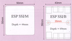 | |
| ESP SSI/120AC | ESP SSI/140AC | |
| Temperature range | -40 to +70آ°C | -40 to +70آ°C |
| Connection type | Screw terminal | Screw terminal |
| Conductor size | 16mm | 16mm |
| Earth connection | Screw terminal | Screw terminal |
| Volt free contact | Connect via screw terminal with conductor up to 2.5mm (stranded) | |
| weight - unit - packaged |
0.5kg 0.6kg |
0.5kg 0.6kg |
| Dimensions image |
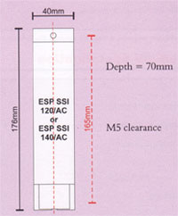 | |