FURSE_Lightning protection device FURSE_ ESP 415 M2ŃÇüESP 415 M4

Product No´╝ÜPro2009414101915
Product Model´╝ÜESP 415 M2ŃÇüESP 415 M4
UpdateTime´╝Ü
Views´╝Ü1791

Details´╝Ü
![]() For customers who demand a protector rated for a maximum surge current greatly in excess of the probable worst case (BS 6651, IEEE C62.41).
For customers who demand a protector rated for a maximum surge current greatly in excess of the probable worst case (BS 6651, IEEE C62.41).![]() Suitable for three phase (346-484V) supplies, whatever their supply current.
Suitable for three phase (346-484V) supplies, whatever their supply current.![]() For a maximum surge current rating of 60kA (unit total 240kA) use ESP 415 M2.
For a maximum surge current rating of 60kA (unit total 240kA) use ESP 415 M2.![]() For a maximum surge current rating of 120kA (unit total 480kA) use ESP 415 M4.
For a maximum surge current rating of 120kA (unit total 480kA) use ESP 415 M4.
Application
Use these units at the main low voltage distribution board for extra high surge current protection. Typical uses include the protection of:
![]() computer equipment
computer equipment![]() transmitter/receiver systems
transmitter/receiver systems![]() uninterruptible power supplies (UPS)
uninterruptible power supplies (UPS)![]() drives and inverters
drives and inverters![]() programmable logic controllers (PLC)
programmable logic controllers (PLC)![]() medical equipment
medical equipment
Features and benefits
![]() Designed to protect and survive in lightning intense environments.
Designed to protect and survive in lightning intense environments.
![]() Very low let-through voltage restricts dangerous transient overvoltages to below the damage levels of equipment circuitry.
Very low let-through voltage restricts dangerous transient overvoltages to below the damage levels of equipment circuitry.
![]() Protection between all sets of conductors (phase to neutral, phase to earth and neutral to earth) ensures total protection, closing all transient paths to equipment.
Protection between all sets of conductors (phase to neutral, phase to earth and neutral to earth) ensures total protection, closing all transient paths to equipment.
![]() Extra high maximum surge current of 60kA (240kA unit total ) for ESP 415 M2 and 120kA (480kA unit total) for ESP 415 M4.
Extra high maximum surge current of 60kA (240kA unit total ) for ESP 415 M2 and 120kA (480kA unit total) for ESP 415 M4.
![]() Repeated protection in lightning intense environments with 20 years predicted lifetime.
Repeated protection in lightning intense environments with 20 years predicted lifetime.
![]() Innovative new SovtripÔäó multiple thermal disconnect technology, anticipates standards authorities future demands, for safe disconnection from faulty or abnormal supplies (without compromising protective performance).
Innovative new SovtripÔäó multiple thermal disconnect technology, anticipates standards authorities future demands, for safe disconnection from faulty or abnormal supplies (without compromising protective performance).
![]()
![]()
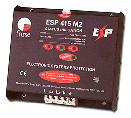
![]() Three way visual indication of protection status.
Three way visual indication of protection status.
![]() Advanced pre-failure warning so you need never be unprotected.
Advanced pre-failure warning so you need never be unprotected.
![]() Remote indication facility allows pre-failure warning to be linked to a building management system, buzzer or light.
Remote indication facility allows pre-failure warning to be linked to a building management system, buzzer or light.
![]() Changeover active volt free contact enables the protector to be used to warn of phase loss (ie power failure, blown fuses etc).
Changeover active volt free contact enables the protector to be used to warn of phase loss (ie power failure, blown fuses etc).
![]() Unique flashing warning of potentially fatal neutral to earth supply faults (caused by incorrect earthing, wiring errors or unbalanced conditions).
Unique flashing warning of potentially fatal neutral to earth supply faults (caused by incorrect earthing, wiring errors or unbalanced conditions).
![]() Robust steel housing.
Robust steel housing.
![]() Simple parallel connection.
Simple parallel connection.
![]() Protector base provides ultra low inductance earth bond to metal panels.
Protector base provides ultra low inductance earth bond to metal panels.
![]() Convenient holes for flat mounting.
Convenient holes for flat mounting.
![]() Compact size for installation in the power distribution board.
Compact size for installation in the power distribution board.
![]() Straightforward, comprehensive installation instructions with every unit.
Straightforward, comprehensive installation instructions with every unit.
![]() Maintenance free.
Maintenance free.
![]() 5 year warranty.
5 year warranty.
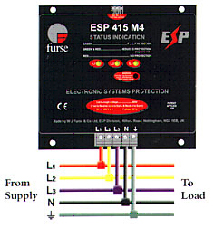
Installation
Install in parallel, within the power distribution board, either on the load side of the incoming isolator, or on the closest outgoing way to the incoming supply. Connect with very short connecting leads, to phase(s), neutral and earth.
On supplies over 100 amps, phase/live connecting leads should be fused with a either a 63 or 100 amp high rupture capacity (HRC) fuses, a switchfuse, MCCB or type C MCB.
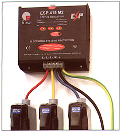
Parallel connection to three phase star (4 wire and earth) supplies.
Parallel connection of ESP 415 M1 or ESP 208 M1 to three phase star (4 wire and earth) supplies.
Suitable accessories
Where the protector can not be incorporated within the panel use the wbx m2 enclosure for the ESP 415 M2 or the wbx m4 for the ESP 415 M4.
Electrical specification
|
|
ESP 415 M2 |
ESP 415 M4 |
|
Nominal voltage (RMS) |
415V |
415V |
|
Working voltage (RMS) |
346 - 484V |
346 - 484V |
|
Frequency range |
40 - 60Hz |
40 - 60Hz |
|
Current rating (supply) -direct connection to supply -connect via series fuses to supply |
<200A >200A |
315A 315A (See installation instructions |
|
Leakage current (to earth) |
<500┬Ás |
<1,000┬Ás |
|
Indicator circuit current |
<20mA |
<40mA |
|
Volt free contact -current rating -nominal voltage (RMS) |
Screw terminal 1A 250V |
Screw terminal 1A 250V |
Transient specification
|
|
ESP 415 M2 |
ESP 415 M4 |
|
Let-through voltage (all conductors)┬╣ 6kV 1.2/50┬Ás open circuit voltage, 3kA 8/20┬Ás short cut current to: BS 6651:1999 Appendix C, Categories C-low and B-High IEE C62.41-1991┬▓ Location Categories C1 and B3 SS CP 33:1996 Appendix F AS 1768-1991 Appendix B, Category B UL1449 mains wire-in |
590V |
570V |
|
4kV 1.2/50┬Ás open circuit voltage, 2kA, 8/20┬Ás short circuit current to: IEC 1000-4-5:1995 |
560V |
540V |
|
2kV 1.2/50┬Ás open circuit voltage, 1kA 8/20┬Ás short circuit current |
510V |
480V |
|
5kA 8/20┬Ás to NFC 61-740 |
670V |
650V |
|
2.5kA 8/20┬Ás to BS EN 60099-1:1994 |
580V |
560V |
|
6kV 0.5┬Ás 100kHz ring wave, 500A to: IEEE C62.41-199F Location Category B3 AS 1768-1991 Appendix B, Category B |
490V |
460V |
|
Maximum surge current┬│ -between any two conductors -total unit to earth |
60kA 240kA |
120kA 480kA |
1 The maximum transient voltage let-through the protector throughout the test (+/-5%), phase to neutral, phase to earth and neutral to earth.
2 Formerly IEEE 587 and ANSI C62.41.
3 Tested with 8/20┬Ás waveshape to BS 6651:1999 Appendix C. Note: The electrical system, external to the unit, may constrain the actual current rating achieved in a particular installation.
Mechanical specification
|
|
ESP 415 M2 |
ESP 415 M4 |
|
Working temperature |
-40┬░C to +70┬░C |
-40┬░C to +70┬░C |
|
Connection type |
Screw terminal |
Screw terminal |
|
Conductor size (stranded) |
25mm┬▓ |
50mm┬▓ |
|
Earth connection |
Screw terminal |
Screw terminal |
|
Volt free contact |
Connect via screw terminal with conductor up to 2.5mm┬▓ (stranded)
| |
|
Weight -unit -packaged |
2.35kg 2.5kg |
3.9kg 4.2kg |
|
Dimensions |
 | |
Download´╝Ü
 ESP415M2_M4.pdf